I wrote a C++ header file to facilitate the co-operation of those two libraries. This file enables the conversion / casting of OpenCV and Qt types e.g.:
The lectures during my last semester were largely focused on digital image processing. Combining this with the inspiration for 3D printing, I gathered through my trip though South Korea, resulted in the following seminar paper. Seminars are a compulsory part of our curriculum which I like due the self-contained work and the ability to pick an individual topic.
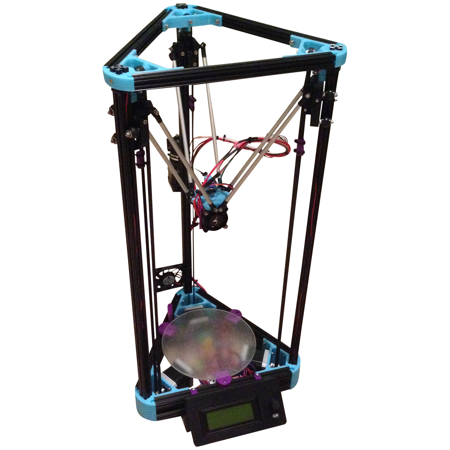
Over the past year, I’ve built my own Kossel 3D printer. The Mini Kossel is based on a novel parallel delta kinematic which was developed by Johann C. Rocholl, a Google engineer from Germany.
This paper is targeting the automation of solder paste dispensing onto printed circuit boards by using computer vision and RepRap robots.
Two of the main challenges for PCB prototyping are the time-consuming setup of involved machines and their economic feasibility for small laboratories and hobbyists. This paper tries to offer solutions for both of these issues:
The complex setup process of industrial machines can be accelerated by computer vision. It is preferable to automate this process as far as possible to enable the operation by untrained personnel and hobbyists. The workflow can be further simplified by not relying on external CAD data. This includes: detection of components, pads and footprints; mapping between available components and footprints and planning of shortest tool paths.
The adaption of proven 3D printers allows to lower the costs for such machines. The lightweight and fast kinematics of parallel 3D-delta robots like the RepRap Mini Kossel are perfectly suited for the assembly of PCBs. Only the print head has to be exchanged between the individual steps of the process.
This work presents a workflow to control DIY 3D printers for the purpose of PCB assembly. By using cheap and easy-obtainable parts like proven RepRap 3D printers, this technique is viable for small laboratories, FabLabs and hobbyists. During the seminar, a analysis and control software for RepRap printers was written. Hence, we focus on the overall workflow and tools and less on algorithms and theory.
Here, the task of solder paste dispensing was chosen to be explored in detail. This work establishes the groundwork for more complex task like the pick and placing of electronic components.
2 Motivation
The ongoing miniaturization of electronic products like smartphones and Ultra Books has led to a new form factor for electronic components. Surface-mounted devices (SMD) are already widespread in electronic design and production. As a result, previously used through-hole components are gradually phased out. This miniaturization of SMD components is an ongoing trend and raises the barrier for hobbyists to produce PCBs themselves. Soldering and placement of 0401-sized resistors or BGA packages is not possible by hand any longer.
This work is motivated by the vision to build an all-in-one machine for the complete process of prototype PCB assembly (PCBA). To accelerate the development process and to reduce the costs, all of these tasks can be handled by a single workbench 3D printer / CNC mill. The PCB production process roughly can consists of the following steps:
Isolation milling or pen plotting of PCB traces
Drilling of holes and contours
Solder paste dispensing for SMD pads with a syringe
Pick-and-place of SMT components with vacuum
Soldering with hot air, a hot plate or by a laser
For the scope of this paper, the process of solder paste dispensing was chosen. This task offers the biggest margin to profit from computer vision. Industrial mass production uses stencils to apply solder paste onto the PCB. For small prototype assemblies the fabrication of stencils is not worthwhile. Therefore, solder paste is applied manually with a pressurized syringe, which is hold by hand.
The dispensing of solder paste requires the knowledge exact solder pad positions and dimensions. Traditionally, this information is exported by CAD design tools and is required to produce the stencils.
But sometimes the CAD data is not available or stored in an inaccessible proprietary format. This paper presents techniques to gather the pad locations and dimensions by means of computer vision.

 As a follow-up to the previous post, I’d like to present some code which I think might be helpful for other Qt / OpenCV projects as well.